Drawing
Hour Lines with Elliptical Coordinates
In ancient Greece the most noted astronomers were often the most famed mathematicians as well. Astronomical problems were both the source and the most sophisticated application for much mathematical research. These two endeavors intersected especially in the study of conic sections and their use in sundial layout.
Conic sections, the circle, the ellipse and the hyperbola, account for both the visual elegance and mathematical sophistication of sundials. The face of equatorial dial radiates its hour lines on the simplest and most eloquent of forms, the circle. On vertical and horizontal dials these lines radiate according to the curves of the circle’s sleeker cousin and the subject of this article, the ellipse. The hyperbola, in its turn, defines datelines traced by the gnomon’s tip.
Constructive geometry
The study of curves using the computational aids of analytic geometry did not arrive until the 17th century after algebraic methods were introduced to Europe from the Middle East. Instead ancient astronomer/mathematicians and their Renaissance heirs used constructive methods to determine hour lines. They tackled all geometric problems armed only with a straightedge and compass (and sometimes a square to speed things up). Nevertheless, they accurately plotted the correct path of time.
Fortunately constructive methods persist and still find their greatest usefulness – as they have for centuries -- in design and building.
Master carpenters who coped with Greek revival styles during the 18th and early 19th centuries employed a variety of constructive methods to create the ornate curves these styles demanded. Handbooks like Asher Benjamin’s The American Builder’s Companion compiled these techniques for carpenters to reference.
The 1827 6th edition of Benjamin’s architectural classic cites five methods for constructing ellipses. Of these the coordinate method most applies to dialing. It plots the ellipse such that each point defines the radiation of an hour line. Further, it can easily be related to the exact latitude and longitude as well as the precise incline and recline of a dial. Also called the point-wise construction, an adaptation of this method is demonstrated below. Benjamin’s original method is illustrated in figure 11.
Whether this method was known in ancient Greece can not be determined based on surviving texts. The name used by Benjamin implies that it derived from analytic geometry, which had introduced the coordinate system. However, several of the surviving investigations by Greek mathematicians into geometric curves, use trigonometric approaches and some display the intuition, if not the computation, of calculus.
Elliptical geometry
The coordinate method provides a means to accurately stretch a circle into an ellipse. A spotlight shining straight down will appear circular on a flat surface, but if tilted at an angle to the surface this light will project into an elongated circle, or ellipse. Lowering the angle of projection will further stretch the ellipse. Ellipses are classified according to this angle of projection: a 42° ellipse indicates an oval produced by a projection angle of 42° to the surface.
An ellipse can also be classified as to the proportion of its elongation, or major axis, to its width, or minor axis. A 42° ellipse and a 1.5 ellipse are nearly the same.
Gnomonic geometry
Equatorial dials parallel the apparent path of the sun and their gnomon’s shadows describe direct analogs of the sun’s circular motion. One hour or 15° of the sun’s progress yields a corresponding 15° of movement of the shadow. However, vertical and horizontal dials lie on a plane other than that of the sun (figure 2). Their shadows distort such that they sweep wide arcs early or and late in the day and narrow arcs at midday. This is because they radiate on elliptical rather than circular arcs: radials on the broader sides of an ellipse spread more than do those at the narrower ends.

Figure 1/ Dividing a circle into 24 segments (hour lines for an equatorial dial).
Draw two perpendicular diameters in the circle, dividing
it into four segments. Set the compass at the end points of each diameter
and strike arcs -- equal to the radius of the circle -- which intersect
its perimeter. Connect all eight intersections to the center. The circle
is now divided into 12 equal (30? ) angles. Spread the compass to the length
of a chord segment and bisect one of the 30? angles. Beginning at the intersection
of the bisector and the circle, use the compass as a divider and strike
30? chords around the circle.

Figure 2/ Projection of an equatorial dial face onto a horizontal plane
The hour lines of an equatorial dial radiate on a circle.
When projected onto a horizontal face, the rays distort elliptically. The
vector of projection follows the angle of the gnomon, which in turn equals
the latitude. The angular distortion of the ellipse, therefore, equals
the latitude of the dial.
On a horizontal dial the degree of the ellipse, which describes these arcs, equals the degree of latitude of the dial’s location. On a vertical dial the degree of this ellipse of radiation equals the complement of the latitude angle, or the co-latitude. Thus, a 42° ellipse will determine the radiation of hour lines on a horizontal dial at 42° latitude. Similarly it takes a 48° ellipse to layout the hour lines of a vertical dial at the same latitude.
To determine the ellipse of radiation, only the relative lengths of its major and minor axes need be known. Exact size is unnecessary, since the radials and not the perimeter of the ellipse are required.
A means to figure these lengths constructively is to draw a gnomonic triangle for the selected latitude. Construct the right triangle ABC such that Ð BCA equals the latitude. In figure 2 this angle is 42° and Ð BAC is 48°, or the colatitude. Now draw line BD at a right angle to the hypotenuse AC. BD is the length of the minor axis of a 42° ellipse where BC is the major axis and may be assigned a value of 1. BC:BD then equals approximately1.5. Correspondingly BD and AB are the minor and major axis of a 48° ellipse. AB:BD equals approximately 1.35. (Those with a background in trigonometry and with a scientific calculator handy can also use the formulas 1/sin 42 and 1/sin 48 to derive the exact proportions).

Figure 3/ Gnomonic triangle for Chicago, IL (42? North)
This triangle may be viewed as the profile of a gnomon
seen from the west. Line AC, the hypotenuse and the shadow-casting edge
of the gnomon, inclines northward. Line AB lies in a vertical plane, while
line BC lies in a horizontal plane. By the principles of gnomonic geometry
line BD parallels the equator and lies in the plane of an equatorial dial.
By these same principles line AC parallels the Earth’s axis and line AB
continues on through its center.
This triangle will serve double duty as the gnomon for both a horizontal and a vertical dial (figure 4). If its horizontal leg abuts a horizontal surface, it becomes the gnomon of a horizontal dial. Mounted on a south-facing wall by its vertical leg, it operates as the gnomon of a vertical dial. In both cases the hypotenuse of the triangle remains the shadow-casting edge.

Figure 4/ Vertical and horizontal gnomons for Chicago, IL (42° North)
Congruent right triangles serve as gnomons for vertical
and horizontal dials at the same latitude. This is because the shadow-casting
edge of a gnomon must remain parallel to the earth’s axis.
Hour line construction
The gnomonic triangle holds all the information necessary to draw hour lines by the elliptical coordinate method.
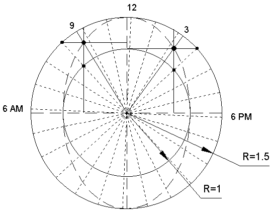
For a horizontal dial, draw two concentric circles such that the inner circle has the radius BD and the outer circle has the radius BC (figure 4). On a vertical dial the outer circle will have the radius AB. Draw two diameters, one for each circle and perpendicular to one another. The longer diameter will become the major axis of the ellipse and the noon line of the dial; the shorter diameter will become the minor axis and the 6 AM - 6 PM hour lines. It is convenient to orient the major axis vertically on the drawing to correspond to north on the dial.
Next draw radials set at 15° intervals (see figure 5 below). These are equivalent to the hour lines of an equatorial dial and are the basis for drawing the corresponding hour lines on a horizontal or vertical dials.

Choose a radial and draw a line through its intersection with the outer circle and perpendicular to the longer diameter. A quick way to do this is to draw the line through both the intersection and its mirror. (In figure 5 the radial is the 9 AM line and this line connects the intersections at 9 and 3 o’clock). Repeat this procedure through the intersection of the radial with the inner circle and line perpendicular to the shorter diameter. The intersection of these two lines will give the coordinate for the same hour on an elliptical radiation. A line from this point to the center of the circles will be the hour line. Continue this construction for each radial and the series of points generated will describe an ellipse. Figure 6 illustrates this for a 42° ellipse.

Applying the coordinate method to each of the 24 radials
in figure 5 will plot a series of points lying on a perfect 42° ellipse.
Each point also determines the elliptical radial for each hour.
Longitude adjustment
Adjust for longitude by rotating the circular radials prior to constructing the elliptical radials. If the longitude of the dial is west of a time meridian rotate the radials to the west from north, or counterclockwise. Rotate east, or clockwise, if its longitude is east of the meridian. A vertical dial mirrors this process.
Figure 7 delineates a horizontal dial construction, which includes this adjustment for Chicago, IL. To account for Chicago’s longitude of approximately 87.5°, 2.5° east of the Central Time Zone’s meridian, the circular radials must rotate 2.5° clockwise. The ellipse, however, remains oriented north to south, so that the major and minor axes are no longer hour lines.

Draw a line through the intersection of a radial and the outer circle such that the line is parallel to the minor axis and perpendicular to the major axis. Then draw a line through the intersection of the same radial and the inner circle such that the line is parallel to the major axis and perpendicular to the minor axis. The intersection of these two lines is the coordinate point determining the hour line. This is essentially the same as the previous construction, but without the symmetry to simplify things.
Reclining and inclining dials, direct north/south
The hour lines of north/south reclining and inclining dials also radiate elliptically. The ellipse of radiation will vary in relation to the degree the dial face inclines or reclines.
An inclining dial can be regarded as a vertical dial, which either tilts forward or backward, that is, southward or northward. In terms of the distribution of hour lines, a forward incline is equivalent to moving the dial south by as many degrees latitude as the dial tilts from 90°. Thus, the layout of a dial with a forward incline of 13° and located at 42° latitude adjusts to that of a vertical dial at 29° latitude. Its ellipse o f radiation is 61°, or the colatitude of 29°. A backward incline in effect moves the dial north in latitude. A 13° incline northward in a dial at 42° latitude will equal a vertical dial at 55° latitude. Its ellipse of radiation is 35°.

Figure 8/ Gnomonic triangle for 42° North with reclining and inclining lines.
Lines are drawn for reclines and inclines of 13°.
These lines substitute for lines AB and BC as major axes in their respective
hour line construction.
Similarly, a reclining dial sloping to the north lays out like a horizontal dial moved to the north by degrees of latitude equal to the degrees of slope. A slope to the south has the same net effect on the dial layout as moving the dial to the south.
Figure 8 shows the construction of 13° inclines and reclines over the gnomonic triangle for 42° North latitude. Just as in the constructions above BD remains as the minor axis of all of the ellipses of radiation. All of the other lines are major axes on the various dials. BW, for example, represents the major axis in laying out a dial having a north incline, while BY denotes the major axis on a north recline. BX and BZ are major axes on a south incline and on a south recline, respectively. Adust for latitude by the same method used on vertical or horizontal dials.
On CAD
Not surprisingly, basic CAD programs can execute all this very rapidly. Draw a circle and divide it evenly with 24 radials or 12 diameters. Make sure two of the diameters are horizontal and vertical. (If needed, make longitude adjustments at this point. Select the entire group and rotate clockwise or counterclockwise as necessary.) Select all and re-scale the Y-axis by the proportion of the desired ellipse of radiation. Use the formula 1/sin x, where x equals the latitude for horizontal dials or the colatitude for vertical dials. In the case of reclining and inclining dials, use the adjusted latitude and its colatitude. This completes the layout.
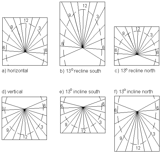
Figure 9 shows the ellipses and the hour lines for each of the dials discussed above and sited at Chicago. The equatorial dial was laid out first and then copied and scaled on TurboCAD 4 to produce each of the other layouts.

All of these layouts began as a single circular layout
for the face of an equatorial dial. This layout was rotated 2.5° east
to adjust for longitude and then scaled along the vertical axis using CAD.
The top three lengthen in proportion to latitude with +/- 13° adjustments
for the reclines. The bottom three proportion in respect to the colatitude
with similar adjustments for the inclines. The determining angles and scales
are: a) 42° (1.49), b) 29° (2.06), c) 55° (1.22), d) 48°
(1.35), e) 61° (1.14), and f) 35° (1.74).
At the extremes: equatorial and polar dials
All north/south dials radiate hour lines elliptically except equatorial and polar dials. Yet these dials, too, are governed by elliptic geometry: they represent the extreme cases of elliptical geometry, the 90° ellipse and the 0° ellipse.
The circle, which governs the radiation of equatorial dials, is classified as a 90° ellipse. Its major and minor axes are equal. The hour lines of an equatorial dial, then, radiate on a 90° ellipse. Since a horizontal dial at the North Pole, 90° North, has a gnomon angle of 90°, it is an equatorial dial.
As the angular measure
of an ellipse diminishes, so does the length of its minor axis (figure
10). At 0°
the minor axis equals 0 and the ellipse collapses into a straight line.
All that remains of the ellipse is its major axis.

A horizontal dial at the Equator, or 0° latitude, will then radiate as a 0° ellipse. The gnomon’s 0° angle sets it flat on the surface, while the hour lines draw together into a bundle of parallel lines that read as one. On the face of it, this is absurd – one line does not a sundial make. Should the gnomon rises above the dial surface, however, the bunched lines will spread, revealing the parallel line pattern of a polar dial. At the Equator a horizontal dial is a polar dial.
Since vertical dials
use the complementary angles of horizontal dials the reverse holds true.
A vertical dial at the Equator equals an equatorial dial, while at the
North Pole it equals a polar dial.
The astronomers who
observed the angles and movement of the sun and mathematicians who studied
conic sections in ancient Greece knew all this. Their design of dials and
their graphic experiments using constructive geometry revealed that the
Earth was round and just how big it was. For the sharpest of them, these
experiments led to the size and distance of the moon and to the notion
that it is, in fact, the Earth that is orbiting the sun.
APPENDIX
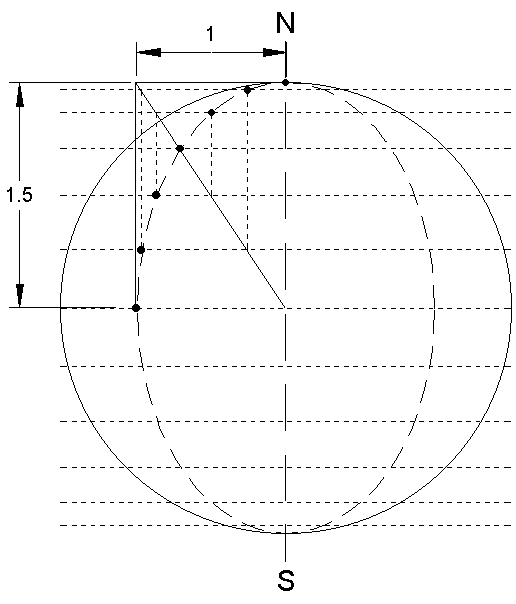
POINT-WISE METHOD from Asher Benjamin’s The American Builder’s Companion:

Figure 11/ Alternate method of plotting elliptical hour lines (42° North)
Divide the circle into 24 equally spaced points. Draw
chord lines through these points perpendicular to the meridian (north/south)
line. Construct a rectangle whose long side is the due north radius of
the circle and whose short side equals the minor axis of the desired ellipse.
Draw the diagonal of that rectangle which terminates at the center of the
circle. Where this diagonal intersects the nearest chord, initiate a line
parallel to the meridian and extend to the farthest chord. Repeat, working
outward on the diagonal and inward on the chords to plot the ellipse.