Topics -- Design Phase, Real Use Cases, Interaction
Diagrams
(L) 15-17 (B) 27
Analysis Phase
-- emphasis on discovering and understanding the
problem domain
| Aspect of problem domain |
Documented by using |
| Processes |
Use Cases |
| Objects, vocabulary, terms,
concepts |
Conceptual Model |
| System events, operations |
System sequence diagrams |
| System accomplishments |
Contracts |
In a mainframe environment,
a single program does most of the tasks
In an object oriented environment,
interaction between two or more software objects
is required
Object Oriented design phase,
assign responsibilities to the software objects
Real Use Case
Adds the input and output technology
that will be used in the application
-
use pictures of the windows involved
-
describe user interaction with the interface
-
describe changes to the interface or form
presented
In essence,
create a user manual of how the system will look and behave
| Typical Course of Events:
Buy Items -- Version 1 |
| Actor Actions: |
System Response: |
| 1) This use case begins
when a Customer arrives at the POST checkout with items to purchase. |
|
| 2) For each item, the
Cashier types in the Universal Product code in the UPC area (A) of Window-1.
If there is more than one of the same item, the
Cashier can enter the quantity in area (E) of Window-1
The Cashier then presses the "Enter Item" button
(H). |
3) Adds the item information
to the running sales transaction.
The description and price of the current item
are displayed in (B) and (F) of Window-1. |
| 4) When there are no more
items, the Cashier presses the "End Sales" Button (I). |
5) Calculates and presents
the sale total
... etc ... |
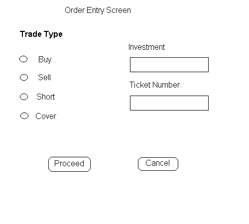
It may be important to stay low-tech, so Screen
Samples can be line drawings
-------------------------------------------------------------------------------------------------------------------
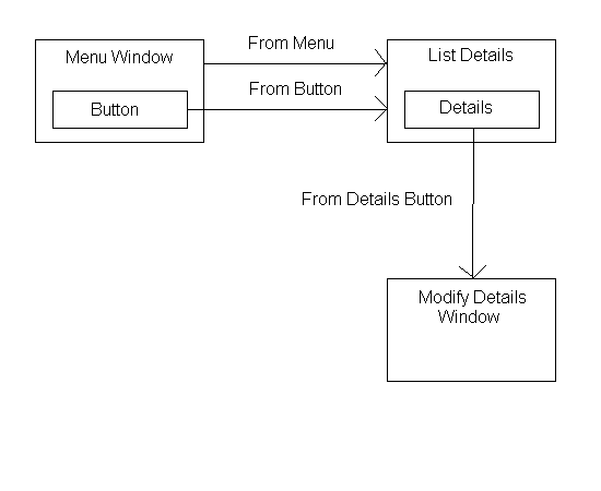
Screen navigation diagrams are needed when multiple
screens are involved
Interaction Diagrams
-
Show the required detailed interactions among objects
over time
-
Determine the distribution of operations among classes
This may include adding objects or attributes to
existing objects.
For each use case, an interaction diagram should
be drawn for
the typical course
all alternate courses
Sequence Diagrams
-- Useful for displaying time sequences,
object activation and concurrent processes
Object icons are shown at the top of the diagram
(laid out left to right)
(these objects exist prior to the start of the operation)
Lifeline -- a dashed vertical line beneath
each object icon
Each object has a lifeline for the length of its
existence.
Activity -- when object is executing a command
is shown by changing
the lifeline to a rectangle.
Messages are indicated by a solid line with
an arrow .
Three kinds of arrows
| Arrow |
Meaning |
Arrow head style |
| simple |
Transfer control to another object |
2-line open |
| synchronous |
Transfer control and wait for answer |
full |
| asynchronous |
Transfer control, donít wait for answer |
half |
Time sequence
Messages closer to the top occur earlier than messages
closer to the bottom
Objects
Created during the operation
have an object icon appear at the time they are
created,
usually with a "create" message
Deleted during the operation
have an X terminating
their lifeline.
(an object can delete itself or be deleted by a
message)
Textual descriptions
of the use case can be included on the left side
of the page
parallel with the diagram messages.
Collaboration Diagrams -- Useful for understanding
the structure and organization of objects
Shown with permanent links connecting objects
A link indicates objects
-
know each other (visibility)
-
can easily send messages to each other (path of navigation).
Messages are indicated with a labeled arrow
on the link
Message sequence is indicated by numbering
-
Simple sequential shows sequence i.e. 1, 2, 3, 4
-
Decimal numbering shows nesting i.e. 1, 1.1, 1.2, 2,
2.1, 2.2, 2.3
Nesting is shown by prepending the incoming message
number to the
outgoing message number
Transition from Analysis to Design
Expand the conceptual model to incorporate infrastructure
classes.
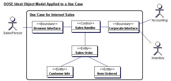
Ivar Jacobsonís Ideal Object Model:
------------------------------------------------------------------------------------------------------------------
Sources:
"The Object Advantage", Ivar Jacobson,
Maria Ericsson, Agneta Jacobson,
ISBN 0-201-42289-1
"Use Case Driven Object Modeling with UML a Practical
Approach"
by Doug Rosenberg with Kendall Scott, ISBN 0-201-43289-7
"Understanding UML The Developerís Guide with a Web-Based
Application in Java" by Paul Harmon and Mark Watson, ISBN 1-55860-465-0
------------------------------------------------------------------------------------------------------------------
The Ideal Object Model
-
perform an analysis of the narrative text of each use
case
-
identify a first-guess set of objects that will participate
in the use case
-
then classify these objects into the following three
types:
-- Boundary, Entity, and Control.
1) Boundary Objects (Presentation)
Windows, screens and other interface things
Boundary Objects
2) Entity Objects (Storage)
Objects from the domain model
Entity Objects need to "outlive"
use case execution
-
contain stable data that does not change often
-
store data, fetch data, perform fundamental computations
-
frequently includes things like forms, orders, checks,
etc.
-
entity names should be names from the domain model
-
usually outlive any single dialogue or interaction
-
may be found in multiple use cases
-
often map to database tables and files.
-
require persist storage databases
-
entity objects may talk to controllers and other entity
objects.
Make entity classes for each object of the problem
domain involved in the process.
3) Control Objects (Application logic)
Connection between boundary and entity objects.
"Control" objects may remain as infrastructure
objects in the solution or be discarded if their operations are more appropriate
as operations of entity or boundary objects.
Control Objects
-
application logic, business rules and policies
-
do not endure as a standalone class
-
also called "handlers"
-
usually responsible for managing a specific use case
-
Life span is the duration of a transaction or use case
-
capture the application logic of a use case
-
serve as the "glue" between boundary objects and entity
objects.
-
capture frequently changing business rules
-
used during analysis to serve as place holders to capture
functionality
-
most are converted into operations associated with either
boundary or entity objects
-
Controllers can talk to boundary, controller or entity
objects
The idea is to localize later changes to design
objects without disrupting the user interface or database schema.
Make at least one control class for managing the
use case
(if the interfaces are complex, create one control
per each interface class)
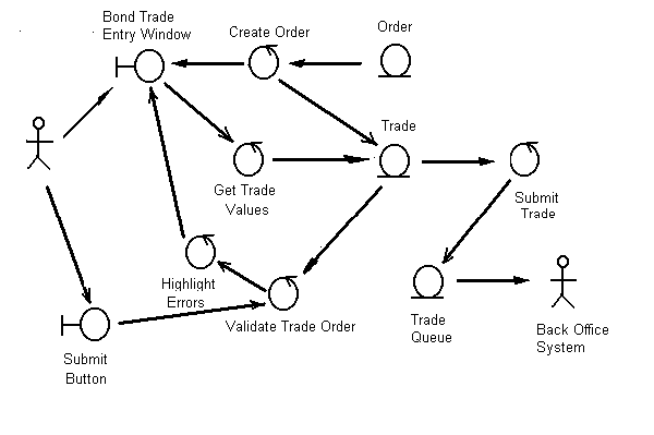
4) Validate completeness by walking through scenarios
(Robustness Analysis)
If it is not possible to fulfill the requirements
of the use case, determine what objects are missing and start over.
Check that there are
1. Small number of controllers per use case.(2-5)
2. Arrows between objects indicate logical associations
and logical flow.
Suggestion.
Each reviewer should be able to do the following
for each use case.
-
read the course of action
-
trace along the associations on the corresponding robustness
diagram.
-
see a clear match between text and picture.
-
Identify all the logical functions that must occur in
the form of control objects.
Based on this analysis it may be necessary to keep
rewriting use case until trace makes sense.
Robustness Analysis uses restricted relationships
between object types
Robustness analysis is a method of
1) Actors can talk only to boundary (presentation)
objects
2) Boundary (presentation) objects can talk only
to control objects and actors.
3) Entity (storage) objects can talk only to control
objects.
4) Control (application) objects can talk to boundary
objects and other control objects.
----------------------------------------------------------------------------------------------------------------
-
5th Assignment (10 points)
-
Real Use Case descriptions of three Use Cases (1 trivial
and 1 nontrivial)
-
Screen Samples & Screen Navigation Diagram where
necessary
-
Conceptual diagrams
-
Ideal Object Diagrams


